


This section describes serveral methods how to adjust the ECM with the help of EcmSpy and overlaps with the same section in the Tuning Guide, therefore only EcmSpy specific topics will be covered here.
For the closed loop and open loop areas a procedure is described for how to do a test ride and log runtime data efficiently, to give good results in a short time.
All test rides must be done with an egine temperature of at least 160 °C to avoid warmup enrichment getting active.
All test rides must be done with an egine temperature of at least 160 °C/320 °Fahrenheit to avoid warmup enrichment getting active.
All process sheets, shown below, follow the same approach: each adjustment cycle is based on a test ride, where runtime data and wideband O2 sensor data, if available, will be logged and analysed. Log file analysis creates and populates the dynamic maps. With the help of these map values the fuel maps will be adjusted manually.
This adjustment cycle will be run repeatedly, until a sufficient precision of the fuel maps is achieved. Generally a deviation of 2% (for example: EGO correction between 0.98 and 1.02 or lambda between 98% and 102%) is a good compromise between effort and result.
Prior to adjusting the fuel maps, some prerequisites are strongly recommended to get reliable and meaningfull results.
All test rides must be done with an egine temperature of at least 160 °C/320 °Fahrenheit to avoid warmup enrichment getting active.
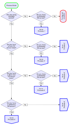
Depending on the equipment available, the tuning processes differ. The process finder tree will lead you to the the recommended work flow to adjust the fuel maps.
Click image for an unscaled view |
With the help of the decision tree, shown in the picture at the left, you can find the tuning process that
fits your configuration and instrumentation. Six different processes will be shown below, each one having a different
requirement, for examples, a front exhaust gas O2 sensor allows to adjust the front cylinder as well as the rear.
All ECM of type DDFI-3 support to monitor and log two (narrowband) O2 sensors and the resulting EGO correction individually,
once configured to do so. This reduces the number of test rides compared to using a single O2 sensor only.
|
If closed loop EGO correction is fully switched off, a wideband O2 sensor is required to adjust the fuel maps. The ECM will continue to read the narrowband O2 sensor's signal (if installed), but will not make adjustments except AFV changes, in case the "open loop learn" feature is still enabled. During the test rides this feature should therefore be disabled also.
Please note: once installed into a header bung, wideband O2 sensors must be connected to the wideband controller and fully powered up when running the engine, as they will get damaged otherwise. Please follow the manufacturer's instructions.
Click image for an unscaled view |
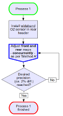
After installing the wideband O2 sensor into the rear headers O2 sensor's boss, a test ride A has to be done to log runtime and lambda data. After the test ride, the log file need to be analysed. The fuel maps will then concurrently adjusted according to the average lambda (Average Lambda 1) cell values. Recommended target values for lambda and detailed informations can be found in section 6.2 of the Tuning Guide Version 2. To speed up fuel map adjustment, only the rear fuel map will be adjusted, but the front fuel map will be locked to changes of the rear by choosing "lock percentaged" from the map lock selector. This way the front map will receive the same percentual changes as applied to the rear map. Repeat this adjustment cycle until the desired result is achieved. |
This way of adjustment is not recommended. The recommended procedure is to adjust front and rear cylinder individually, using a wideband O2 sensor in the rear and front header.
This adjustment process is for all vehicles, where a narrowband O2 sensor is installed in the rear header only and no wideband O2 sensor is available. Following the instructions below help to adjust the closed loop area and the idle region. This stabilizes the AFV and idle speed (DDFI-2 and DDFI-3 have the idle closed loop feature enabled by default, DDFI doesn't). As no wideband O2 sensor is available, the open loop regions can not be adjusted.
Click image for an unscaled view |
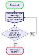
Collect and store runtime data by performing a test ride A. After the ride, analyse the log file. The fuel maps will then adjusted concurrently according to the average EGO correction map's (Average Correction 1) cell values. The target is to get an average EGO correction near 1.0 (= 100%) all over the closed loop area and the idle area, if desired. To speed up fuel map adjustment, only the rear fuel map will be adjusted, but the front fuel map will be locked to changes of the rear by choosing "lock percentaged" from the map lock selector. This way the front map will receive the same percentual changes as applied to the rear map. Repeat this adjustment cycle until the desired result is achieved. |
This way of adjustment is not recommended. The recommended procedure is to adjust front and rear cylinder individually, using a O2 sensor in the rear and front header. But for many stock bikes this will be the only method of choice, unless an additional O2 sensor bung has been installed in the front header. Always leave the "Open Loop Learn" feature enabled after using this method.
This adjustment process is for all vehicles with a narrowband O2 sensor installed in the rear header only and where a wideband O2 sensor is available. Following the instructions below help to adjust the closed loop area and the idle region, followed by adjustments for the open loop areas.
Please note: once installed into a header bung, wideband O2 sensors must be connected to the wideband controller and fully powered up when running the engine, as they will get damaged otherwise. Please follow the manufacturer's instructions.
Click image for an unscaled view |
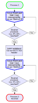
1.) Fuel map adjustments start with a test ride B to collect and store runtime data. After the ride the logfile is analysed and the fuel maps get adjusted concurrently according to the average EGO correction map's (Average Correction 2) cell values. The target is to get an average EGO correction near 1.0 (= 100%) all over the closed loop areas. These adjustments are continued, until the desired precision is achieved. Please make sure that AFV is stable when riding in different areas of the closed loop area before proceeding to step 2. If the AFV is still fluctuating (without changing altitude or without heavy climatic air pressure changes), repeat the first step until the problem is solved. 2.) Once closed loop is adjusted, the narrowband O2 sensor in the rear header will be replaced by the wideband O2 sensor. Additionally all EGO correction is switched off by unchecking the "Enable Closed Loop" box in the "Closed Loop" tab. The next step requires to mark the throttle grip for all load rows above the closed loop area, usually the topmost 4 rows in the fuel maps. Then a test ride A is performed to collect and store runtime as well as wideband lambda data.
After the ride the logfile is analysed and the fuel maps get adjusted concurrently according to the average lambda map's (Average Lambda 1) cell values. Recommended target values for lambda and detailed informations can be found in section 6.2 of the Tuning Guide Version 2. To speed up fuel map adjustment, only the rear fuel map will be adjusted, but the front fuel map will be locked to changes of the rear by choosing "lock percentaged" from the map lock selector. This way the front map will receive the same percentual changes as applied to the rear map. Repeat this adjustment cycle until the desired results are achieved. |
After all adjustments are done, the wideband O2 sensor will be removed and replaced by the narrowband O2 sensor. The EGO correction is switched on again by checking the "Enable Closed Loop" box in the "Closed Loop" tab.
This way of adjustment is not recommended. The recommended procedure is to adjust front and rear cylinder individually, using O2 sensors in the rear and front header. But for many stock bikes this will be the only method of choice, unless an additional O2 sensor bung has been installed in the front header.
Swapping the O2 sensor requires comparatively much effort. The most wideband O2 sensors are capable to simulate a narrowband O2 sensor, but only when it's planned to use the simulated signal after these adjustment, then it should be used for closed loop adjustments (step 1 of this worksheet) too. In all other cases it is strictly recommended to use those sensors for adjustment runs, that will remain installed later.
If the front header has a O2 sensor boss installed, this process will be chosen for fuel map adjustments. Because deinstalling the O2 sensor in the rear header requires a lot of work, getting a second O2 sensor is a time saving investment. Any single-wire unheated narrowband O2 sensor, easily available in almost every car equipment store, can be used.
By following this worksheet, the closed loop area will be adjusted individually for the rear and the front cylinder. As no wideband O2 sensor is available, the open loop areas can not be monitored and adjusted.
Adjustments per cylinder is the recommended practice, because only so the fuelling for each cylinder will be set correctly. This procedure is used in all following worksheets too.

Click image for an unscaled view |
1.) With a narrowband O2 sensor installed in the rear hader, fuel map adjustments start with a test ride B to collect and store runtime data. After the ride the logfile is analysed and the fuel map for the rear cylinder is adjusted individually according to the average EGO correction map's (Average Correction 1) cell values. The target is to get an average EGO correction near 1.0 (= 100%) all over the closed loop areas. To avoid changing the front cylinder's fuel map also, "unlocked" has to be selected from the map lock selector. ECM of type DDFI-3 can monitor a second narrowband O2 sensor and will calculate EGO correction individually for each cylinder if the "Enable Independent Front CL" checkbox is marked on the "Closed Loop" tab and a narrowband O2 sensor is connected to the ECM at pin 31 of the grey plug. This saves a lot of time because only half the number of test rides is required now and step 2 can be skipped. The average EGO correction for the front cylinder will then be shown in the second EGO correction map (Average Correction 2). Repeat this adjustment cycle until the desired precision is achieved. 2.) When all adjustments are done for the rear cylinder, the ECM is connected to the narrowband O2 sensor installed in the front header. To avoid unwanted side effects it is also recommended, to set all rows of the "Front Cylinder Correction" table to 100% fuel. With a narrowband O2 sensor installed in the front hader, fuel map adjustments start with a test ride B to collect and store runtime data. After the ride the logfile is analysed and the fuel map for the front cylinder is adjusted individually according to the average EGO correction map's (Average Correction 2) cell values. The target is to get an average EGO correction near 1.0 (= 100%) all over the closed loop areas. To avoid changing the rear cylinder's fuel map also, "unlocked" has to be selected from the map lock selector. Repeat this adjustment cycle until the desired precision is achieved. |
After all adjustments are done, the O2 sensor in the front header is removed (where applicable) and the rear O2 sensor is reconnected to the ECM. If the bike is running smoother with the front instead of the rear sensor installed, there are no reasons to not keep this configuration. Instead of the rear, the front cylinder will then provide the O2 signal the ECM uses for calculating the EGO correction, which is then applied to both cylinders as before (unless the individual closed loop feature is enabled). By changing fuel in the "Front Cylinder Correction" table, the front fuelling can be changed easily for further adjustments, if necessary.
This workflow allows to adjust fuel for each cylinder individually and covers the closed loop area as well as the open loop areas as a wideband sensor is available to monitor lambda values. An O2 sensor boss in the front header is required also. The wideband sensor is installed in place of the narrowband sensor. If two wideband sensors are available, test rides can be saved because EcmSpy can monitor up to two wideband sensors simultaneously.
The individual fuel adjustment for the front and the rear cylinder, covering all regions, is the recommended procedure.
Please note: once installed into a header bung, wideband O2 sensors must be connected to the wideband controller and fully powered up when running the engine, as they will get damaged otherwise. Please follow the manufacturer's instructions.

Click image for an unscaled view |
1.) The first step requires to adjust the closed loop area for both cylinders, as described in process 4. Please follow the instructions given there to individually adjust the front and rear cylinder. Please make sure that AFV is stable when riding in different areas of the closed loop area before proceeding to step 2. If the AFV is still fluctuating (without changing altitude or without heavy climatic air pressure changes), repeat the first step until the problem is solved. 2.) After the closed loop area is adjusted, the rear narrowband O2 sensor is reconnected to the ECM and the front narrowband sensor is replaced by a wideband sensor, which is then connected to the PC or netbook. To avoid unwanted side effects it is also recommended to set all rows of the "Front Cylinder Correction" table to 100% fuel. All load values above the closed loop area, usually the topmost 4 rows in the fuel maps, must be marked at the throttle grip. EGO correction needs to be disabled by unchecking the "Enable Closed Loop" box in the "Closed Loop" tab. The next steps depend on the availability of one or two wideband O2 sensors. A) 1 wideband O2 sensor available: A.1.) Perform a test ride A to collect and store runtime data from the ECM and lambda data from the wideband O2 sensor. After the ride the logfile is analysed and the fuel map for the front cylinder is adjusted individually according to the average lambda value map's (Average Lambda 1) cell values. Recommended target values for lambda and detailed informations can be found in section 6.2 of the Tuning Guide Version 2. To avoid changing the rear cylinder's fuel map also, "unlocked" has to be selected from the map lock selector. Repeat this adjustment cycle until the desired results are achieved. When all adjustments are done for the front cylinder, the wideband O2 sensor is installed in the rear header. The sensor bung in the front header can be closed with a plug now as it is not needed any further. A.2.) Again perform a test ride A as describe in step 2.1 above. Collect data, analyse the logfile and adjust the rear fuel map's open loop areas now according to the average lambda value map's (Average Lambda 1) cell values. Recommended target values for lambda and detailed informations can be found in section 6.2 of the Tuning Guide Version 2. To avoid changing the front cylinder's fuel map also, "unlocked" has to be selected from the map lock selector. Repeat this adjustment cycle until the desired results are achieved. B) 2 wideband O2 sensors available: A wideband O2 sensor will be installed in each header. If not done already, EGO correction needs to be disabled by unchecking the "Enable Closed Loop" box in the "Closed Loop" tab. B.1.) Perform a test ride A to collect and store runtime data from the ECM and lambda data from the wideband O2 sensors. After the ride the logfile is analysed and the fuel maps for the front and the rear cylinder are adjusted individually according to the average lambda value map's cell values. If the wideband sensor was connected to the PC as described in the instructions below the sensor type selector, the front O2 sensor data is shown in the "Average Lambda 1" map, rear O2 sensor data in the "Average Lambda 2" map. Recommended target values for lambda and detailed informations can be found in section 6.2 of the Tuning Guide Version 2. To avoid changing the other cylinder's fuel map also, "unlocked" has to be selected from the map lock selector. Repeat this adjustment cycle until the desired results are achieved. |
After all adjustments are done, the wideband O2 sensor in the rear header is replaced by the narrowband O2 sensor, which is connected to the ECM again. A wideband O2 sensor in the front header (if installed) is removed or replaced by a second narrowband O2 sensor, depending on the bike's setup. EGO correction is enabled also by checking the "Enable Closed Loop" box in the "Closed Loop" tab. If the bike is running smoother with the narrowband O2 sensor installed in the front instead of the rear header, there are no reasons to not use this configuration. Instead of the rear, the front cylinder will then provide the O2 signal the ECM uses for calculating the EGO correction, which is then applied to both cylinders as before (unless the individual closed loop feature is enabled). By changing fuel in the "Front Cylinder Correction" table, the front fuelling can easily be changed for further adjustments, if necessary.
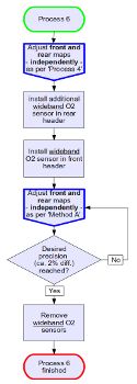
If the rear or the rear and the front headers are equipped with slave O2 sensor bosses, please follow this worksheet. If two wideband sensors are available, test rides can be saved because EcmSpy can monitor up to two wideband sensors simultaneously.
The individual fuel adjustment for the front and the rear cylinder, covering all regions, is the recommended procedure, as it allows to map each cylinder for it's specific fuel requirements.
Please note: once installed into a header bung, wideband O2 sensors must be connected to the wideband controller and fully powered up when running the engine, as they will get damaged otherwise. Please follow the manufacturer's instructions.
Click image for an unscaled view |
1.) The first step requires to adjust the closed loop area for both cylinders, as described in process 4. Please follow the instructions given there to individually adjust the front and rear cylinder. Please make sure that AFV is stable when riding in different areas of the closed loop area before proceeding to step 2. If the AFV is still fluctuating (without changing altitude or without heavy climatic air pressure changes), repeat the first step until the problem is solved. 2.) After the closed loop area is adjusted, the rear narrowband O2 sensor is reconnected to the ECM and both narrowband sensors are replaced by wideband sensors, which are then connected to the PC or netbook. To avoid unwanted side effects it is also recommended to set all rows of the "Front Cylinder Correction" table to 100% fuel. All load values above the closed loop area, usually the topmost 4 rows in the fuel maps, must be marked at the throttle grip. EGO correction needs to be disabled by unchecking the "Enable Closed Loop" box in the "Closed Loop" tab. Perform a test ride A to collect and store runtime data from the ECM and lambda data from the wideband O2 sensor. After the ride the logfile is analysed and the fuel map for each cylinder is adjusted individually according to the average lambda value map's (Average Lambda 1 for the front, Average Lambda 2 for the rear cylinder) cell values. Recommended target values for lambda and detailed informations can be found in section 6.2 of the Tuning Guide Version 2. To avoid changing the other cylinder's fuel map also, "unlocked" has to be selected from the map lock selector. Repeat this adjustment cycle until the desired results are achieved. |
After all adjustments are done, the rear wideband O2 sensors is replaced by a narrowband O2 sensor, which is connected to the ECM again. The wideband O2 sensor in the front header is removed or replaced by a second narrowband O2 sensor, depending on the bike's setup. EGO correction is enabled also by checking the "Enable Closed Loop" box in the "Closed Loop" tab. If the bike is running smoother with the narrowband O2 sensor installed in the front instead of the rear header, there are no reasons to not use this configuration. Instead of the rear, the front cylinder will then provide the O2 signal the ECM uses for calculating the EGO correction, which is then applied to both cylinders as before (unless the individual closed loop feature is enabled). By changing fuel in the "Front Cylinder Correction" table, the front fuelling can easily be changed for further adjustments, if necessary.