Mono is the open source implementation of Microsoft's .NET platform and a runtime environment similar to Java. When using Mono, the mono application (called "assembly") is running inside a virtual machine. As the assembly code is platform independent, it can run on different machines and operating systems such as Windows, Linux or MacOS. They can be started with a double-click on the desktop icon as usual, but the user interface will in many cases have a bit different look and feel.
Before running the EcmSpy for Mono software, a Mono Runtime Environment has to be installed on the computer. The Mono installer can be downloaded from the Mono download area. Please follow the installation instructions provided with the download.
MODIFYING YOUR ECM WILL INVALIDATE WARRANTY, COULD DAMAGE YOUR ENGINE AND IS PERFORMED ENTIRELY AT YOUR OWN RISK! IN THE U.S.A., CANADA AND EUROPE, FEDERAL LAW MAKES IT ILLEGAL FOR ANYONE TO TAMPER WITH, DISCONNECT, REMOVE OR OTHERWISE RENDER INOPERATIVE ANY AUTOMOTIVE EMISSIONS RELATED CONTROL DEVICE. IN GENERAL, THE ENTIRE FUEL SYSTEM AND ALL ITS INDIVIDUAL COMPONENTS (INCLUDING THE EFI ECM) ARE CONSIDERED 'EMISSIONS RELATED CONTROL DEVICES'. THE PENALTIES FOR TAMPERING CAN BE SUBSTANTIAL.
If you modify your ECM, you may be legally obliged to notify your insurance company. It may also be illegal in some countries to ride on the road with a modified ECM. It should also be stated that modifying your ECM will certainly void your manufacturer's warranty! All numbers shown in lists, tables and maps are purely fictious and MUST NOT be applied to any existing bike.
If EcmSpy for Mono is to be installed on a Microsoft Windows system, log into your personal download area, then download the file "EcmSpy_Mono_1.1-Setup.exe", which is the installer application for the EcmSpy program.
Start the installation procedure by double-clicking the installer application. The installation procedure is quite similar to every other done on a Windows system. If no suitable Mono runtime was found on your computer, you will get an informational screen and the installation will stop then.
Next the license agreement will be displayed. Please read the license agreement carefully before proceeding. You must accept the terms of this agreement before continuing with the installation. Click the "Next" button to continue.
The following panels will ask for the destination path for the EcmSpy software (default path is "C:\Program Files\EcmSpy_Mono") and the name of the Start Menu folder ("EcmSpy for Mono"). Change the default entries if you want and confirm by clicking the "Next" button.
Now the setup program copies all the required files to the destination folder. After the copying is done the PATH variable will be adjusted, if it didn't contain the Mono path already. A message box will inform you about that. You will have to log off and on again after the installation is finished to activate this new setup. No restart will be required.
You will find a new directory in your "My Files" folder, named "ecmspy" containing three subfolders:
Please note when upgrading from version 1.0 to version 1.1: The installer will copy all files found in the old folders (commonly: "C:\Program Files\EcmSpy_Mono\...") to the newly created folders in your personal area. Please check that all files you want to work with found their way into the new folders and copy missing files manually.
Please log off and on now if the path had been adjusted during installation. You will find a new shortcut on the desktop, double-click it to start the EcmSpy for Mono program. On slow computers the startup will take up to 15 seconds while the Mono runtime engine is started, which is then executing the EcmSpy assembly. You will notice a lot of harddisk activity during startup, please be patient and do not double-click the shortcut again.
To read and fetch EEPROM data from a file or the ECM, a database is required which holds all information how the EEPROM of your bike's ECM is laid out. You will have to create a key file (push the "Register" button in the menu bar) and run the software activation to get a working database.
If you try to connect to your bike's ECM and this ECM type has not been activated, an error message like the one below will pop up and tell you the installed ECM type:

The ECM type shown in the message box should be marked when filling in the activation form.
Once your donation has been confirmed, the database installer will be available in your personal download area. Download and execute the database installer as you did with the application installer to set up the database for your ECM type. You will need a password to start installation. The password is also shown in the files list in your personal download area. After the database has been installed correctly, the EcmSpy for Mono application has all information available to connect to the ECM and retrieve a copy of the EEPROM data.
If you plan to connect your computer to the ECM, you have to get a connection lead and probably install some drivers to make the cable work and set up a virtual COM port to talk to. Please follow the installations guide provided with the driver software in that case.
Linux? What the heck is Linux?
The menu bar contains several buttons (from left to right):

|
"Connect" - connect to the ECM |

|
"Execute" - start polling live data from the ECM |
 |
"Log" - toggles logging live data to file |
 |
"Info" - show application version and license agreement |
 |
"Register" - creates the public key file (required for activation) |
 |
"Quit" - quit application |
Some buttons possibly look different than shown above in your operating system, but the order stays equal.
The status bar displays some short messages (in it's left half) and indicates a few operating modes by showing or hiding an icon:
 |
"Connected" (connected to the ECM) |
 |
"Executing" (polling live data) |
 |
"Logging" (writing live data to file) |

|
"Error" (the ECM signals a trouble code) |
 |
"Read Log" (reading log data from a log file) |
Some images possibly look different than shown above in your operating system, but the order stays equal.
The overview pane will always be shown when the EcmSpy assembly is started. No entries contain any data, as the application is not connected to an ECM yet.
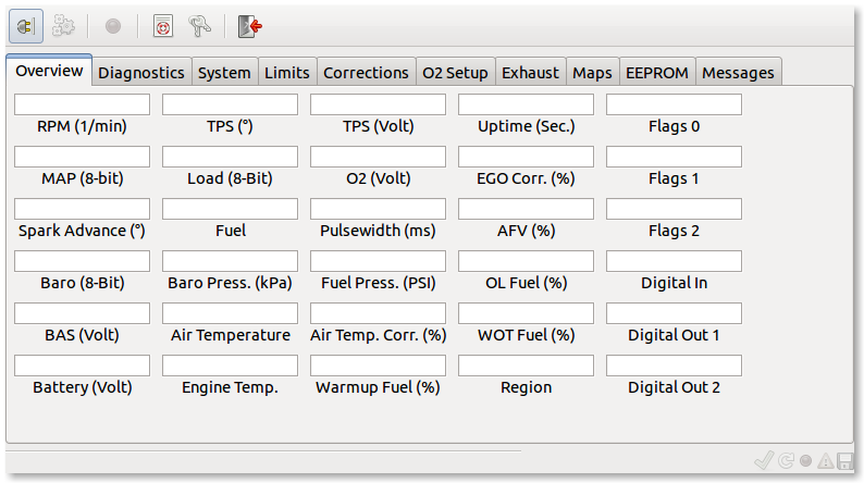
Click image for an unscaled view
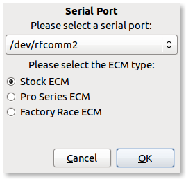
After clicking the "Connect" button, the connection dialog pops up. Select the port you are using for the connector cable and choose the ECM type installed in your bike. Click the "OK" button if you want to connect to the ECM and automatically fetch the EEPROM data now, otherwise click the "Cancel" button to close the port selection dialog and remain unconnected. If you change your mind, you can always push the "Connect" button to connect to the ECM later.
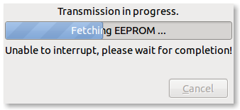
If no EEPROM copy has loaded into the application yet (e.g. from a file), it will automatically fetched from the ECM as soon as the connection is established and the ECM type is supported by the application. A moving bar will keep you updated on the progress of reading data from the ECM:
Once connected to the ECM and the "Execute" menu button is pushed, the now empty text fields will then show live data, polled continously from the ECM.
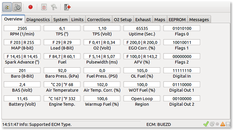
Click image for an unscaled view
A second click on the "Execute" button toggles the button and stop polling. Even when polling is active you can change to other tabs (System, Diagnostics, ...), but it's not possible to start another action that requires a communication with the ECM (e.g. clear trouble codes). In this case, you will have to stop polling live data first. If a trouble code is set while polling is active, the warning sign will be switched on also. Time to stop polling and to proceed to the diagnostic pane then.
The diagnostics window will accept input only when connected to an ECM, otherwise no button will respond to mouseclicks. You can fetch the trouble codes from the ECM (current errors as well as stored errors), run diagnostic tests on several devices, perform a TPS reset and reset the AFV to 100% in case it has run amok and prevents the engine from starting. Depending on the ECM type and the actual setup only the rear AFV (the one available with DDFI and DDFI-2) or front and rear AFV (DDFI-3 only) will be set to a new value. The new AFV will be written to the ECM immediately and will also stored in the active copy of the EEPROM that got fetched when connecting to the ECM.

Click image for an unscaled view
If you recorded a log file, this can be used to (basically) check the O2 sensor. It's very important to cover the closed loop area as good as possible. The engine and O2 sensor must have reached their operating temperature, therefore the distance ridden should not be less then 25 mls or 40 km, and the duration not less then 30 minutes

O2 sensors are subjects to wear, and their responsiveness as well as the variation in voltage drops. On this pane, a narrowband O2 sensor's data will be read from a log file and statistically evaluated. Also, when reading the log file, a few additional maps are filled with data.

Click image for an unscaled view |
|
Click image for an unscaled view
All device tests suitable for a special ECM type are described in the Service Manual. Select a test from the list and click the "Run Test" button. Unless the engine is running or the selected device is not available, a popup will appear while the test is running. The ECM does not send a test result, so it's your task to check if the tested device is working as expected.
To perform a TPS reset (DDFI and DDFI-2 only), follow the instructions and push the "Reset" button. The TPS voltage signaled to the ECM with a fully closed butterfly will then be stored in the EEPROM. The entry "TPS Zero Voltg." shows the value stored in the EEPROM, not the actual TPS voltage. This can be looked up at the overview tab.
To perform a TPS reset for DDFI-3 equipped bikes please follow the instructions in the service manual.
The system window is divided into three panes, which show the general configuration, the error mask configuration and some system information (readonly).

Click image for an unscaled view
The general configuration is devided into system, noise abatement and airbox pressure sensor configuration. Each tab offers a number of checkboxes, that can be marked (switched on) or unmarked (switched off) to enable or disable a specific feature or setup. The various settings are explained in the following lists:
 |
|
 |
|
 |
|
 |
|
The error mask configuration controls which errors will make a trouble code set and the CEL lit. The error mask configuration is split into several sections, each covering a part of the potential sensor, actor or ECM errors. Trouble codes not supported by the ECM (e.g. front O2 sensor, MAP sensor) will be deactivated and not respond to mouse clicks.
The system information pane shows some detailed data describing the ECM. Not all data is available for all ECM types.
All RPM and engine temperature limits as well as cooling fan switching points are configured in the limits window. Like the system configurion window this one is divided into three panes also. The RPM and temperature limits panes are divided into several subpanes as theses configurations are quite substantial, especially the RPM limits.

Click image for an unscaled view
When the engine hits a RPM or temperature limit, one of three different limits - depending on their "severity" - might apply:
 |
 |
Limits can apply directly when they are hit, and are called fixed limits then, or they get applied after a countdown had been running before, then they are called delayed limits. Limits and timers have a trigger value where they are activated and a reset value, where they are released.

|

|
RPM limits are different for high and low speed conditions (they differ dependent on the gear, the bike is in) and DDFI-3 type ECMs also apply a cold engine RPM limit.
 |
 |
Temperature limits consist of the limits themselfs (the temperatures, that will trigger a limit) and conditions, that control how and when limits may get tightened or relased. The conditions also control when the CEL starts and stops signaling an overheating condition.
The third and rightmost panel controls the cooling fan action, either with the engine switched off ("Key-Off") or on ("Key-On
 |
|
The fuel correction setups are bundled in the corrections window, which is devided into several panes also. The left panes contain those tables, which keep data for corrections regarding to engine temperature. The most common table will probably be the warmup enrichment table, accompanied by the front cylinder correction and the idle correction, which is similar to the warmup correction, but active in idle only.

Click image for an unscaled view
The right pane shows tabs for other corrections that are not temperature dependent or needed more than only one table.

Click image for an unscaled view |
|

Click image for an unscaled view |
|

Click image for an unscaled view |
|
The O2 sensor setup window contains all O2 sensor related configurations, sensor data as well as closed loop and calibration mode area definitions.

Click image for an unscaled view
The left pane shows the O2 sensor's hardware setup, voltages which signal a rich, lean or error condition. The activation or deactivation of the O2 sensor will also be configured here.

|
|
The right pane is divided into several tabs for configuration of the closed loop and calibration mode areas,the wideband O2 sensor setup and a (experimental) O2 sensor analysis area.
For ECM types that support the simultaneous operation of separate rear and front O2 sensors (DDFI-3 only), the closed loop operation can be limited to use the rear cylinder's sensor only, or switched off completely. Bikes that have two O2 sensors installed, will by default run an independend closed loop for the rear and the front cylinder.

Click image for an unscaled view |
|

Click image for an unscaled view |
|

EcmSpy for Mono supports up to two wideband O2 sensors, logged simultaneously with ECM live data. To enable wideband logging, select the manufacturer from the upper and the serial port, the wideband sensor is connected to, from the lower list. Currently Innovate and PLX are the only manufacturers supported. Next toggle the "Activate" button to start reading wideband data. As soon as live data aquisition is switched on and logging to file active also, wideband O2 sensor data will be added to the text (.msl extension) log file.
The AMC (active muffler control) setup is available on this page. The valve in the silencer is opened and closed depending on engine speed and (optionally) load. The AMC setup supports three switching points.

Click image for an unscaled view
The actuator is triggered by passing a RPM switchpoint, but the action can be suspended if a load condition has been set and is not fulfilled. In that case the valve position won't change. If the control voltage polarity is reversed, the switching point results are reversed too, instead of opening the valve it will now be closed. This allows two different control pattern. The default is to close the exhaust valve at idle or middle speed and open it at low or high engine speed.
The maps and the EEPROM pages are very similar, therefore get both covered in one section. The largest area in these windows is the data area, where the map or the EEPROM data will be shown, with editing buttons at the bottom. Data can be loaded from and saved to a file, and EEPROM data can also be fetched from or burnt into the ECM.
If a log file providing EGO correction, AFV or lambda data has been read and the fuel maps have not been touched until then, saving fuel maps to file will also save the additional averaged data from the log file. These map files could later be added to the "My Maps" area to set up your own map repository.

Click image for an unscaled view

Click image for an unscaled view
As more than one fuel map or spark advance table is stored within the EEPROM data, a pull-down menu lets you choose a map. Fuel maps and timing tables can be adjusted in three different kinds, selectable from the pull-down menu at the lower left:
To edit a cell, point to and click it. You will see the cell highlighted and it's value is shown in the spin-button entry at the bottom. This entry always shows values in decimal, EEPROM data got a text field at the left showing the value in hexadecimal also. By clicking the up and down spinbuttons or by typing a new number the entry can be changed. There are also some editing buttons available, to aid in adjusting the cell. The new value get's written back to his cell by clicking the "=" button right aside the entry or by hitting return. To "unhilight" a cell, click into the header row or into some free space around the data grid.
Sometimes changes do not get reflected immediately (e.g. boundary changes), in that case click into any cell to start editing and confirm the unchanged value by pushing the "=" button, this forces a map redraw with the current values.
To load or save a map or EEPROM data, push the apropriate button. A file selector appears and let's you choose a file. The last used directory will be stored and used again the next time you want to open or save a file. EcmSpy for Mono accepts .epr and .xpr files for EEPROM data and .msq files for map data. Text files (.txt) for EEPROM data are not supported.
After an EEPROM copy has been loaded into EcmSpy for Mono (either fetched from the ECM or read from a file), theses maps are filled with data from the EERPOM copy:
If a log file has been read (see also O2 Sensor Analysis), additional maps will get filled with data (if available):
Average Correction Front, Average Correction Rear

Click image for an unscaled view
This map shows the average EGO correction. EGO correction, read from the log file, will only be taken into account if the engine runs in closed loop, therefore values will be limited to the closed loop area of the fuel map (and one cell outside). The EGO correction value, as stored in the log file, will be averaged that way, that cells "nearby" get it added with a higher weight than "distant" cells. If the runtime data do not provide EGO correction for the front cylinder, the values from the rear cylinder are copied to the front cylinder's map.
Average AFV Front, Average AFV Rear
Click image for an unscaled view
This map shows the average AFV, as calculated when the engine is running in calibration mode. Therefore values in this map will be limited to the calibration area (and one cell outside) of the fuel map. The average AFV is calculated and weighted the same way as the average EGO correction. If the runtime data do not provide AFV data for the front cylinder, the values from the rear cylinder are copied to the front cylinder's map.
Hits Front, Hits Rear
Click image for an unscaled view
The distribution of readings from the log file across the fuel map. If a operating point lies between several cells, each cell touched will get one unweighted hit added.
Average Lambda 1, Average Lambda 2

Click image for an unscaled view
An average wideband O2 sensor lambda value, if wideband O2 data was available when writing the log file (see also Wideband O2 Sensors). These values are taken into account only, if the engine is not in acceleration or deceleration mode. When adding lambda values, the same weighting as for EGO correction is applied. If the runtime data do not provide data for two O2 sensors, the values from the first O2 sensor are copied to the second O2 sensor's map. If two O2 sensor are connected, it is assumed that sensor 1 monitors the front, and sensor 2 the rear cylinder.
The ecmspy.com website offers a new feature, called "My Maps", which allows users to upload map files, sorted by adjustment runs and versions. This area is open to all users who activated their copy of EcmSpy for Mono
The idea was to provide an easy way to save different map files, for comparison and documentation purposes. This feature also complies with the recommended procedure as described in the Tuning Guide, version 2. If available in the map file, optional dynamic maps of the average EGO correction or wideband O2 sensor results will be shown too. The possibility to compare two map versions online makes it easy to find differences between maps whithout the need to copy map data into other tools like spreadsheet applications or similar.
"My Maps" manages all data as tuning activities ("Adjustment run"), consisting of multiple map versions. Each version can be commented (the current date by default) and is linked to a map file, which can also be downloaded again.

Click image for an unscaled view
After logging in into "My Maps" all existing adjustment runs will be listed. To open a specific run, mark it and click the "Open" button. Adjustment runs can be added and deleted, too.

Click image for an unscaled view
Once an adjustment run has been opened, all related map versions are shown in a list. The first version is usually the stock mapping, the last version the final map and all versions in between document the tuning process. EEPROM adjustments, that are not stored in a map, can be described in an text area. All adjustments to the EEPROM data should be written down here, to keep records of the tuning process, it is also a good idea to record environmental effects (e.g. air pressure) here that have an impact on tuning.

Click image for an unscaled view
The detail view of a map version shows all maps, that are available in the uploaded map file. Map files can be deleted and uploaded again, if e.g. dynamic maps were not available when a map version was added to an adjustment run and will be updated later.

Click image for an unscaled view
In addition to the map details a map comparison is available also. This is a fast and helpful way to compare two different versions of the same adjustment run, to get an impression of fuel changes and their impacts on EGO correction or wideband lambda values.
This section describes serveral methods how to adjust the ECM with the help of EcmSpy for Mono and overlaps with the same section in the Tuning Guide, therefore only EcmSpy specific topics will be covered here.
For the closed loop and open loop areas a procedure is described for how to do a test ride and log runtime data efficiently, to give good results in a short time.

Click image for an unscaled view |
To log runtime data in an open loop area, the map or the part of the map, which is to be adjusted,
will be processed at a fixed TPS. To do so, each load, that is present in the map (y axis values) will
be indicated by a mark at the throttle grip. During the test ride the throttle will be positioned on
each mark, starting with a low speed and the highest possible gear, and held until the speed stops increasing.
Overrun conditions should be avoided as the mixture will change. With the throttle held steadily each line in
the map will be run through from left (low rpm) to right (high rpm) and all runtime and lambda data for this
specific load condition will be recorded. Repeat each run at least three times.
|
All test rides must be done with an egine temperature of at least 160 °C to avoid warmup enrichment getting active.

Click image for an unscaled view |
Adjusting the Closed Loop area, located in the center of the fuel maps, follows a different approach. In this case the test ride should span the closed loop area as much as possible. The more cells of the map are used, the more meaningfull will be the averages calculated from the log data. Vary load and engine speed, but ride calmly and avoid hard acceleration or overrun conditions. A test ride should last at least 30 minutes (time is more significant then distance) to collect a sufficient number of data records. It takes some time to establish an EGO correction for each operating point (load-rpm combination). An easy way to cover the map is to ride at a steady speed in a high gear for 15-20 seconds, then gear down keeping the speed until rpm reach the closed loop rpm threshold (about 5000 rpm for XB engines). All logged EGO correction data will be averaged and filled into the appropriate map, when the log file is analyzed with EcmSpy. For a significant result, each cell should show more than 100 hits (number of records collected). To check a cell's hits, click the cell in the "Average Correction" map and look for the number in the cell's status bar: 
Click image for an unscaled view Cell entries with a hit value below 100 should be used with care only. The calibration and closed loop areas have to be adjusted before the open loop areas, because the AFV is calculated from EGO correction and controls the open loop mixture. A well adjusted calibration area will result in a stable AFV, which is a good foundation for open loop adjustments using a wideband O2 sensor. |
All test rides must be done with an egine temperature of at least 160 °C to avoid warmup enrichment getting active.
All process sheets, shown below, follow the same approach: each adjustment cycle is based on a test ride, where runtime data and wideband O2 sensor data, if available, will be logged and analyzed. Log file analysis creates and populates the dynamisch maps. With the help of these map values the fuel maps will be adjusted.
This adjustment cycle will be run repeatedly, until a sufficient precision of the fuel maps is achieved. Generally a deviation of 2% (for example: EGO correction between 0.98 and 1.02 or lambda between 98% and 102%) is a good compromise between effort and result.
Prior to adjusting the fuel maps, some prerequisites are strongly recommended to get reliable and meaningfull results.

Click image for an unscaled view |
1.) The first and most important task is to backup and savely store the stock EEPROM data. This copy will allow you to come back to a known working setup for the bike in case something goes wrong. 2.) Check the static timing according to the service manual. Static timing will commonly not change unless the Camshaft Position Sensor has been moved. Crankshaft Position Sensors, as found in 2008 and later engines, can't be adjusted at all. 3.) Perform a TPS reset for DDFI and DDFI-2 ECM types:
4.) Do a calibration ride to update the AFV. Write down the actual AFV (it must no necessarily have changed) and multiply the front and rear fuel maps by it. Clear the AFV (push the "Clear" button at the "Diagnostics" tab), but do not block it, as it is important to know if the AFV changes later. 5.) Optional: create a new adjustment run in My Maps, describing the engine setup (airbox changes, exhaust, ...) in the comment area. Add the initial map version to this adjustment run. |
All test rides must be done with an egine temperature of at least 160 °C to avoid warmup enrichment getting active.
Depending on the equipment available, the tuning processes differ. The process finder tree will lead you to the the recommended work flow to adjust the fuel maps.

Click image for an unscaled view |
With the help of the decision tree, shown in the picture at the left, you can find the tuning process that
fits your configuration and instrumentation. Six different processes will be shown below, each one having a different
requirement, for examples, a front exhaust gas O2 sensor allows to adjust the front cylinder as well as the rear.
All ECM of type DDFI-3 support to monitor and log two (narrowband) O2 sensors and the resulting EGO correction individually,
once configured to do so. This reduces the number of test rides compared to using a single O2 sensor only.
|
If closed loop EGO correction is fully switched off, a wideband O2 sensor is required to adjust the fuel maps. The ECM will continue to read the narrowband O2 sensor's signal (if installed), but will not make adjustments except AFV changes, in case the "open loop learn" feature is still enabled. During the test rides this feature should therefore be disabled also.
Please note: once installed into a header bung, wideband O2 sensors must be connected to the wideband controller and fully powered up when running the engine, as they will get damaged otherwise. Please follow the manufacturer's instructions.

Click image for an unscaled view |
After installing the wideband O2 sensor into the rear headers O2 sensor's boss, a test ride A has to be done to log runtime and lambda data. After the test ride, the log file need to be analysed. The fuel maps will then concurrently adjusted according to the average lambda (Average Lambda 1) cell values. Recommended target values for lambda and detailed informations can be found in section 6.2 of the Tuning Guide Version 2. To speed up fuel map adjustment, only the rear fuel map will be adjusted, but the front fuel map will be locked to changes of the rear by choosing "lock percentaged" from the map lock selector. This way the front map will receive the same percentual changes as applied to the rear map. Repeat this adjustment cycle until the desired result is achieved. |
This way of adjustment is not recommended. The recommended procedure is to adjust front and rear cylinder individually, using a wideband O2 sensor in the rear and front header.
This adjustment process is for all vehicles, where a narrowband O2 sensor is installed in the rear header only and no wideband O2 sensor is available. Following the instructions below help to adjust the closed loop area and the idle region. This stabilizes the AFV and idle speed (DDFI-2 and DDFI-3 have the idle closed loop feature enabled by default, DDFI doesn't). As no wideband O2 sensor is available, the open loop regions can not be adjusted.

Click image for an unscaled view |
Collect and store runtime data by performing a test ride A. After the ride, analyze the log file. The fuel maps will then adjusted concurrently according to the average EGO correction map's (Average Correction 1) cell values. The target is to get an average EGO correction near 1.0 (= 100%) all over the closed loop area and the idle area, if desired. To speed up fuel map adjustment, only the rear fuel map will be adjusted, but the front fuel map will be locked to changes of the rear by choosing "lock percentaged" from the map lock selector. This way the front map will receive the same percentual changes as applied to the rear map. Repeat this adjustment cycle until the desired result is achieved. |
This way of adjustment is not recommended. The recommended procedure is to adjust front and rear cylinder individually, using a O2 sensor in the rear and front header. But for many stock bikes this will be the only method of choice, unless an additional O2 sensor bung has been installed in the front header. Always leave the "Open Loop Learn" feature enabled after using this method.
This adjustment process is for all vehicles with a narrowband O2 sensor installed in the rear header only and where a wideband O2 sensor is available. Following the instructions below help to adjust the closed loop area and the idle region, followed by adjustments for the open loop areas.
Please note: once installed into a header bung, wideband O2 sensors must be connected to the wideband controller and fully powered up when running the engine, as they will get damaged otherwise. Please follow the manufacturer's instructions.

Click image for an unscaled view |
1.) Fuel map adjustments start with a test ride B to collect and store runtime data. After the ride the logfile is analyzed and the fuel maps get adjusted concurrently according to the average EGO correction map's (Average Correction 2) cell values. The target is to get an average EGO correction near 1.0 (= 100%) all over the closed loop areas. These adjustments are continued, until the desired precision is achieved. Please make sure that AFV is stable when riding in different areas of the closed loop area before proceeding to step 2. If the AFV is still fluctuating (without changing altitude or without heavy climatic air pressure changes), repeat the first step until the problem is solved. 2.) Once closed loop is adjusted, the narrowband O2 sensor in the rear header will be replaced by the wideband O2 sensor. Additionally all EGO correction is switched off by unchecking the "Enable Closed Loop" box in the O2 sensor setup tab. The next step requires to mark the throttle grip for all load rows above the closed loop area, usually the topmost 4 rows in the fuel maps. Then a test ride A is performed to collect and store runtime as well as wideband lambda data.
After the ride the logfile is analyzed and the fuel maps get adjusted concurrently according to the average lambda map's (Average Lambda 1) cell values. Recommended target values for lambda and detailed informations can be found in section 6.2 of the Tuning Guide Version 2. To speed up fuel map adjustment, only the rear fuel map will be adjusted, but the front fuel map will be locked to changes of the rear by choosing "lock percentaged" from the map lock selector. This way the front map will receive the same percentual changes as applied to the rear map. Repeat this adjustment cycle until the desired results are achieved. |
After all adjustments are done, the wideband O2 sensor will be removed and replaced by the narrowband O2 sensor. The EGO correction is switched on again by checking the "Enable Closed Loop" box in the O2 sensor setup tab.
This way of adjustment is not recommended. The recommended procedure is to adjust front and rear cylinder individually, using O2 sensors in the rear and front header. But for many stock bikes this will be the only method of choice, unless an additional O2 sensor bung has been installed in the front header.
Swapping the O2 sensor requires comparatively much effort. The most wideband O2 sensors are capable to simulate a narrowband O2 sensor, but only when it's planned to use the simulated signal after these adjustment, then it should be used for closed loop adjustments (step 1 of this worksheet) too. In all other cases it is strictly recommended to use those sensors for adjustment runs, that will remain installed later.
If the front header has a O2 sensor boss installed, this process will be chosen for fuel map adjustments. Because deinstalling the O2 sensor in the rear header requires a lot of work, getting a second O2 sensor is a time saving investment. Any single-wire unheated narrowband O2 sensor, easily available in almost every car equipment store, can be used.
By following this worksheet, the closed loop area will be adjusted individually for the rear and the front cylinder. As no wideband O2 sensor is available, the open loop areas can not be monitored and adjusted.
Adjustments per cylinder is the recommended practice, because only so the fuelling for each cylinder will be set correctly. This procedure is used in all following worksheets too.

Click image for an unscaled view |
1.) With a narrowband O2 sensor installed in the rear hader, fuel map adjustments start with a test ride B to collect and store runtime data. After the ride the logfile is analyzed and the fuel map for the rear cylinder is adjusted individually according to the average EGO correction map's (Average Correction 1) cell values. The target is to get an average EGO correction near 1.0 (= 100%) all over the closed loop areas. To avoid changing the front cylinder's fuel map also, "unlocked" has to be selected from the map lock selector. ECM of type DDFI-3 can monitor a second narrowband O2 sensor and will calculate EGO correction individually for each cylinder if the "Enable Independent Front CL" checkbox is marked on the O2 sensor setup tab and a narrowband O2 sensor is connected to the ECM at pin 31 of the grey plug. This saves a lot of time because only half the number of test rides is required now and step 2 can be skipped. The average EGO correction for the front cylinder will then be shown in the second EGO correction map (Average Correction 2). Repeat this adjustment cycle until the desired precision is achieved. 2.) When all adjustments are done for the rear cylinder, the ECM is connected to the narrowband O2 sensor installed in the front header. To avoid unwanted side effects it is also recommended, to set all rows of the "Front Cylinder Correction" to 100% fuel. With a narrowband O2 sensor installed in the front hader, fuel map adjustments start with a test ride B to collect and store runtime data. After the ride the logfile is analyzed and the fuel map for the front cylinder is adjusted individually according to the average EGO correction map's (Average Correction 2) cell values. The target is to get an average EGO correction near 1.0 (= 100%) all over the closed loop areas. To avoid changing the rear cylinder's fuel map also, "unlocked" has to be selected from the map lock selector. Repeat this adjustment cycle until the desired precision is achieved. |
After all adjustments are done, the O2 sensor in the front header is removed (where applicable) and the rear O2 sensor is reconnected to the ECM. If the bike is running smoother with the front instead of the rear sensor installed, there are no reasons to not keep this configuration. Instead of the rear, the front cylinder will then provide the O2 signal the ECM uses for calculating the EGO correction, which is then applied to both cylinders as before (unless the individual closed loop feature is enabled). By changing fuel in the "Front Cylinder Correction" table, the front fuelling can be changed easily for further adjustments, if necessary.
This workflow allows to adjust fuel for each cylinder individually and covers the closed loop area as well as the open loop areas as a wideband sensor is available to monitor lambda values. An O2 sensor boss in the front header is required also. The wideband sensor is installed in place of the narrowband sensor. If two wideband sensors are available, test rides can be saved because EcmSpy for Mono can monitor up to two wideband sensors simultaneously.
The individual fuel adjustment for the front and the rear cylinder, covering all regions, is the recommended procedure.
Please note: once installed into a header bung, wideband O2 sensors must be connected to the wideband controller and fully powered up when running the engine, as they will get damaged otherwise. Please follow the manufacturer's instructions.

Click image for an unscaled view |
1.) The first step requires to adjust the closed loop area for both cylinders, as described in process 4. Please follow the instructions given there to individually adjust the front and rear cylinder. Please make sure that AFV is stable when riding in different areas of the closed loop area before proceeding to step 2. If the AFV is still fluctuating (without changing altitude or without heavy climatic air pressure changes), repeat the first step until the problem is solved. 2.) After the closed loop area is adjusted, the rear narrowband O2 sensor is reconnected to the ECM and the front narrowband sensor is replaced by a wideband sensor, which is then connected to the PC or netbook. To avoid unwanted side effects it is also recommended to set all rows of the "Front Cylinder Correction" to 100% fuel. All load values above the closed loop area, usually the topmost 4 rows in the fuel maps, must be marked at the throttle grip. EGO correction needs to be disabled by unchecking the "Enable Closed Loop" box in the O2 sensor setup tab. The next steps depend on the availability of one or two wideband O2 sensors. A) 1 wideband O2 sensor available: A.1.) Perform a test ride A to collect and store runtime data from the ECM and lambda data from the wideband O2 sensor. After the ride the logfile is analyzed and the fuel map for the front cylinder is adjusted individually according to the average lambda value map's (Average Lambda 1) cell values. Recommended target values for lambda and detailed informations can be found in section 6.2 of the Tuning Guide Version 2. To avoid changing the rear cylinder's fuel map also, "unlocked" has to be selected from the map lock selector. Repeat this adjustment cycle until the desired results are achieved. When all adjustments are done for the front cylinder, the wideband O2 sensor is installed in the rear header. The sensor bung in the front header can be closed with a plug now as it is not needed any further. A.2.) Again perform a test ride A as describe in step 2.1 above. Collect data, analyze the logfile and adjust the rear fuel map's open loop areas now according to the average lambda value map's (Average Lambda 1) cell values. Recommended target values for lambda and detailed informations can be found in section 6.2 of the Tuning Guide Version 2. To avoid changing the front cylinder's fuel map also, "unlocked" has to be selected from the map lock selector. Repeat this adjustment cycle until the desired results are achieved. B) 2 wideband O2 sensors available: A wideband O2 sensor will be installed in each header. If not done already, EGO correction needs to be disabled by unchecking the "Enable Closed Loop" box in the O2 sensor setup tab. B.1.) Perform a test ride A to collect and store runtime data from the ECM and lambda data from the wideband O2 sensors. After the ride the logfile is analyzed and the fuel maps for the front and the rear cylinder are adjusted individually according to the average lambda value map's cell values. If the wideband sensor was connected to the PC as described in the instructions below the sensor type selector, the front O2 sensor data is shown in the "Average Lambda 1" map, rear O2 sensor data in the "Average Lambda 2" map. Recommended target values for lambda and detailed informations can be found in section 6.2 of the Tuning Guide Version 2. To avoid changing the other cylinder's fuel map also, "unlocked" has to be selected from the map lock selector. Repeat this adjustment cycle until the desired results are achieved. |
After all adjustments are done, the wideband O2 sensor in the rear header is replaced by the narrowband O2 sensor, which is connected to the ECM again. A wideband O2 sensor in the front header (if installed) is removed or replaced by a second narrowband O2 sensor, depending on the bike's setup. EGO correction is enabled also by checking the "Enable Closed Loop" box in the O2 sensor setup tab. If the bike is running smoother with the narrowband O2 sensor installed in the front instead of the rear header, there are no reasons to not use this configuration. Instead of the rear, the front cylinder will then provide the O2 signal the ECM uses for calculating the EGO correction, which is then applied to both cylinders as before (unless the individual closed loop feature is enabled). By changing fuel in the "Front Cylinder Correction" table, the front fuelling can easily be changed for further adjustments, if necessary.
If the rear or the rear and the front headers are equipped with slave O2 sensor bosses, please follow this worksheet. If two wideband sensors are available, test rides can be saved because EcmSpy for Mono can monitor up to two wideband sensors simultaneously.
The individual fuel adjustment for the front and the rear cylinder, covering all regions, is the recommended procedure, as it allows to map each cylinder for it's specific fuel requirements.
Please note: once installed into a header bung, wideband O2 sensors must be connected to the wideband controller and fully powered up when running the engine, as they will get damaged otherwise. Please follow the manufacturer's instructions.

Click image for an unscaled view |
1.) The first step requires to adjust the closed loop area for both cylinders, as described in process 4. Please follow the instructions given there to individually adjust the front and rear cylinder. Please make sure that AFV is stable when riding in different areas of the closed loop area before proceeding to step 2. If the AFV is still fluctuating (without changing altitude or without heavy climatic air pressure changes), repeat the first step until the problem is solved. 2.) After the closed loop area is adjusted, the rear narrowband O2 sensor is reconnected to the ECM and both narrowband sensors are replaced by wideband sensors, which are then connected to the PC or netbook. To avoid unwanted side effects it is also recommended to set all rows of the "Front Cylinder Correction" to 100% fuel. All load values above the closed loop area, usually the topmost 4 rows in the fuel maps, must be marked at the throttle grip. EGO correction needs to be disabled by unchecking the "Enable Closed Loop" box in the O2 sensor setup tab. Perform a test ride A to collect and store runtime data from the ECM and lambda data from the wideband O2 sensor. After the ride the logfile is analyzed and the fuel map for each cylinder is adjusted individually according to the average lambda value map's (Average Lambda 1 for the front, Average Lambda 2 for the rear cylinder) cell values. Recommended target values for lambda and detailed informations can be found in section 6.2 of the Tuning Guide Version 2. To avoid changing the other cylinder's fuel map also, "unlocked" has to be selected from the map lock selector. Repeat this adjustment cycle until the desired results are achieved. |
After all adjustments are done, the rear wideband O2 sensors is replaced by a narrowband O2 sensor, which is connected to the ECM again. The wideband O2 sensor in the front header is removed or replaced by a second narrowband O2 sensor, depending on the bike's setup. EGO correction is enabled also by checking the "Enable Closed Loop" box in the O2 sensor setup tab. If the bike is running smoother with the narrowband O2 sensor installed in the front instead of the rear header, there are no reasons to not use this configuration. Instead of the rear, the front cylinder will then provide the O2 signal the ECM uses for calculating the EGO correction, which is then applied to both cylinders as before (unless the individual closed loop feature is enabled). By changing fuel in the "Front Cylinder Correction" table, the front fuelling can easily be changed for further adjustments, if necessary.